Knowledge Graph Technologies Accelerate and Improve the Data Model Definition for Master Data
In the ongoing master data management project the challenge is to create a consolidated golden record of particular business information scattered across multiple systems of different business units. Applying knowledge graph technologies has proven to be an effective means to automatically derive a logical data model for this golden record and improve stakeholder communication.

Software Engineer

Senior Solution Architect
The Master Data Management Challenge
Master data management (MDM) is a technology-enabled discipline in which business and Information Technology work together to ensure the uniformity, accuracy, stewardship, semantic consistency and accountability of the enterprise's official shared master data assets.1 At Zalando we are at an early phase of realising MDM for our internal data assets and we have chosen to do it in a consolidated style.
Typically, MDM projects are started because an organisation does not have a central view to a specific subject matter and, instead, that information, such as the contact details of a business partner, are scattered across systems with each maintaining their own differing or same record of these details. In our practical approach MDM is a set of practises to create a common, shared, and trusted view on data, also called a golden record, for a particular domain. In our MDM project, source systems are identified, their data is consumed, processed through a match and merge process, cleansed and quality assured, and then stored centrally according to a canonical data model. This centrally stored golden record, is then published back to the source systems for consideration and possible correction in their respective systems.
We are currently designing a central MDM component that harmonises the different records into the central and trusted golden record. Its form needs to be defined in a logical data model. This is a set of definitions of tables and columns in which the consolidated record pulled, matched, and merged from the different sources is stored. Deriving this model is usually done manually, which has the following drawbacks:
- The amount of manual work to create the logical data model increases relatively to the number of system tables.
- Usually, the data models are read and created by colleagues from engineering with limited business know-how.
- The communication of the data model of source records and the data model of the golden record is shown as technical and textual definition files (SQL schema or a spreadsheet).
- For business stakeholders that are domain experts the understanding of contents and how they relate to each other is hard to grasp from these technical definition files.
- The domain expert is limited from conveying correctly the knowledge to the engineers creating the data model, which leads to errors and misunderstandings.
Because of these drawbacks, the risk is that a MDM tool is released with a faulty and incorrect model that needs iterations of rework. As the logical data model is a main driver for the effort of creating a MDM tool effecting user interface, processes, business rules, and data storage, this risk might have a large impact and delays the business value delivery.
As the communication between business and engineering about a correct logical data model is happening upon textual technical specification files, an effective and efficient data governance decision making process is hindered, too, which is important to make the golden record also trustworthy.
The logical data model is not the only deliverable in such an MDM project. We also have to deliver the mapping from each system's data model to the golden record's one and define whether mapping can be done directly 1-to-1, or whether it needs to go through some kind of transformation. For example, system A may define an address differently like system B.
System A: Address
- address_line_1
- address_line_2
- address_line_3
System B: Address
- street
- zip_code
- city
- country_code
The golden record data model needs to define the optimal and correct way to store an address object as well as define how the differing systems' data models map to it. If done manually, also this work increases with the number of system tables.
Using Knowledge Graph Technologies
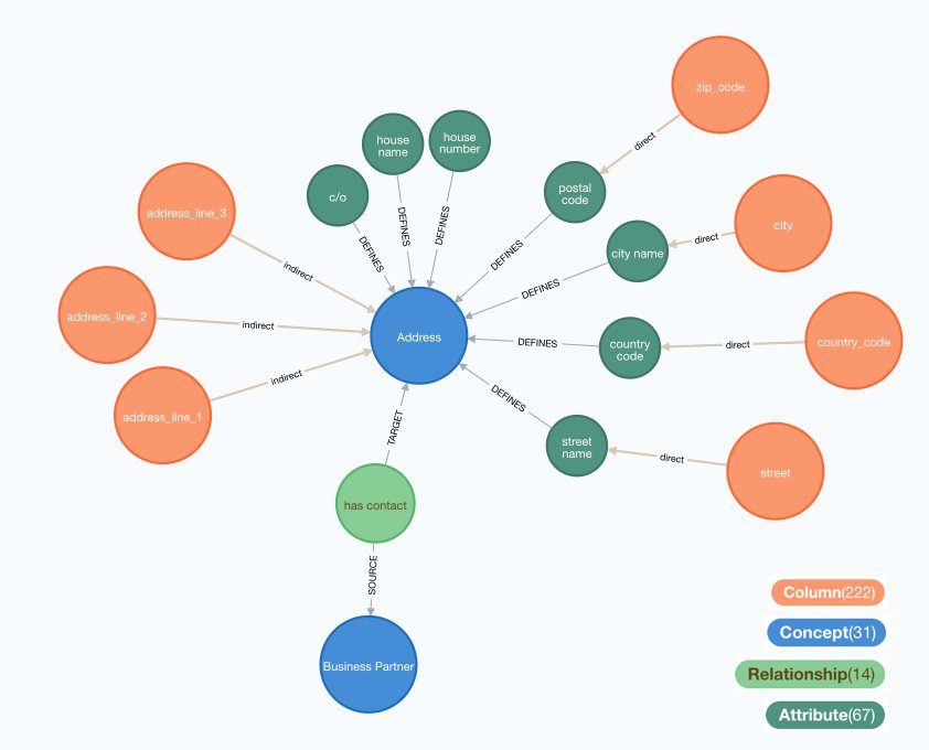
In order to improve this manual definition, we made use of knowledge graph technologies by describing all system's data models in a named directed graph. We then mapped each column of a system to a set of business concepts, such as "address", "contact person", or "business partner". These business concepts have attributes as well as relationships with other concepts. For example, the business partner concept is connected to the address concept as in the image below.2

We are using Neo4J to create these human-readable images about the mappings, since it has, in our opinion, the best look-and-feel in the current landscape of knowledge graph technologies. Most domain experts can read these images much better than the above mentioned data model definition files. Currently, we are mapping tens of tables and hundreds of columns, so creating images manually would generate more manual and error-prone work and that is why it is efficient to generate these images from the knowledge graph. The number in brackets in the colour legend is the total amount of nodes of this type in the knowledge graph.
For the above mentioned example of system A and B storing address information differently, we can model this in the knowledge graph in the following way. Columns from system A, such as address line 1, 2, and 3, map indirectly (one-to-many) to the address concept. This means that these columns need to be processed into the MDM system with a transformation algorithm. Columns from system B, however, map directly (one-to-one) to respective attributes of the address concept. See the image below for an illustration.
Focusing Manual Work Where it Should Be
The only manual work that is done is to record the mapping from systems' tables and columns to business concepts, their attributes, and their relationships. For example, system A and B is mapped in the following way:
System A: Address
- address id -> concept: Address, relationship: has contact (target)
- business partner id -> concept: Business Partner, relationship: has contact (source)
- address_line_1 -> concept: Address
- address_line_2 -> concept: Address
- address_line_3 -> concept: Address
System B: Address
- id -> concept: Address, relationship: has contact (target)
- business partner id -> concept: Business Partner, relationship: has contact (source)
- street -> concept: Address, attribute: street name
- zip_code -> concept: Address, attribute: postal code
- city -> concept: Address, attribute: city name
- country_code -> concept: Address, attribute: country code
And that is all that needs to be done manually. A domain expert can provide us with these definitions and some coordination that the exact same name for concepts, attributes, and relationships is required. This is done by cross-referencing system's business concepts and unifying their wording.
Generating the Logical Data Model
The mapping from systems' tables and columns to business concepts is processed and written into the knowledge graph, which then holds the following types of nodes:
- System, the name of one system owning tables and columns.
- Table, the name of a table from a particular system.
- Column, one column in one system with respective schema definitions, such as data type.
- Concept, a business concept such as Address.
- Attribute, one single data record defining the concepts, such as street name for the address concept.
- Relationship, a connecting information between two concepts flowing from one, the source concept, to the other, the target concept. For example business partner "has contact" address.
The logical data model is then systematically created (via a Python script) from the concepts, attributes, and relationships. Each concept is created with a table of its own, where the columns are all of its attributes and an internal identifier for the concepts. Each relationship also becomes a table of its own with the internal identifiers of the source and target concepts as foreign key columns.
Since the graph contains the record which system's tables and columns contribute to one concept, we can then also generate the so-called transformation data model, which shows how each system's column maps to (directly or indirectly) to the logical data model of the golden record.
By using knowledge graphs for a live-data representation of all systems' logical data models and how they map to a semantic layer of business concepts, we are able to automatically generate the logical data model of the golden record inside the knowledge graph with additional information on how it connects to systems' data model. This enables us to keep a record of data lineage from each system to the golden record and, additionally, to use contemporary knowledge graph visualisation tools to give domain experts a intuitive and understandable representation on how each system is connected to the golden record. We see here two main advantages:
- The dialogue between business and technology in designing the golden record logical data model has improved and accelerated the process of creating a correct model.
- All deliverables, such as the logical data model and the transformation data model can be queried directly from the knowledge graph and do not need to be done manually, which is less error-prone.
We estimate that during the development of the MDM component this approach will keep on saving time for us by forgoing misunderstandings and improving stakeholder communication.
Wikipedia on Master Data Management 23.7.2021 ↩
For knowledge graph experts it is worthwhile to note that because this is a schema for the logical data model, also relationships between concepts are modeled as nodes. This is a deliberate design choice. It enables us to map data model information to relationships. ↩
We're hiring! Do you like working in an ever evolving organization such as Zalando? Consider joining our teams as a Data Engineer!


